360 degree turntable
Several of our projects, RotorCam, the So-Now Sonar, the Infrared Tag Cannon, et al,
are based upon our stepper motor controlled rotating platform,
so we thought we would dedicate one of our pages to it.
This is that page.
THE STEPPER CONTROLLED ROTATING
OMNIDIRECTIONAL TURNTABLE & UNIVERSAL MOUNT
The 'Stepper Controlled Rotating Omnidirectional Turntable and Universal Mount',
or, 'SCROTUM' for short,
allows a platform to swivel through 360 degrees, continuously,
whilst maintaining wired connections between the top and bottom parts.
The video below shows our prototype in action.
First, a question

If the turntable continually turns through 360º, how is it the wires do not get twisted ???
I have to admit, that IS a good question.
To be honest though, I'm disappointed it hasn't been asked sooner.
It is however fundamental to the design of this type of rotating device.
Therefore we will begin by explaining how this works.
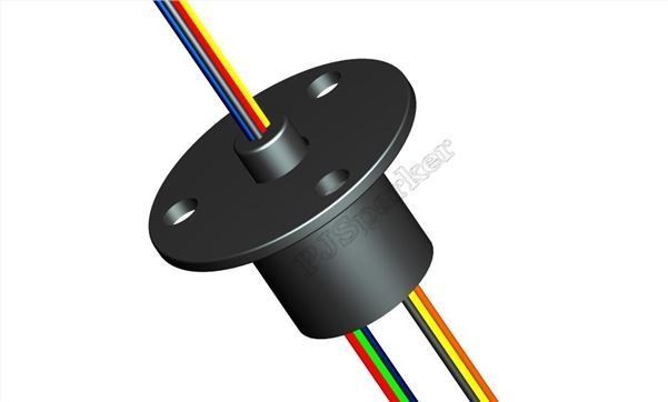
To prevent wires twisting, we need to use a 'slip ring'.
the slip ring

A slip ring is a 'cable management device'.
Wires entering one end are attached to a series of rings which are isolated from each other.
The wires entering or exiting the other end, are attached to contacts, which 'slip' across the surface of the rings.
An electrical contact between a wire entering one end, is maintained with a colour-matched wire at the other end, without twisting the wires when one end of the device is rotated.
The actual witchcraft which goes on inside one of these devices may vary, for instance some are magnetically coupled using coils, but the theory is the same.
As a result of this however, we cannot drive the rotating top of whatever it is we are trying to spin
directly using a motor. The wires could not pass through the axis of the motor.
We therefore use a pair of shafts connected together somehow, one from the motor shaft and another connected to the rotating top.
We could use pulleys, belts, gears or any other means to allow the one to drive the other.
As can be seen in the video, we chose to use pinion gears.
We 3D printed ours for our prototype.
We ordered some pre-formed metal gears for later developments.
Pinion gears
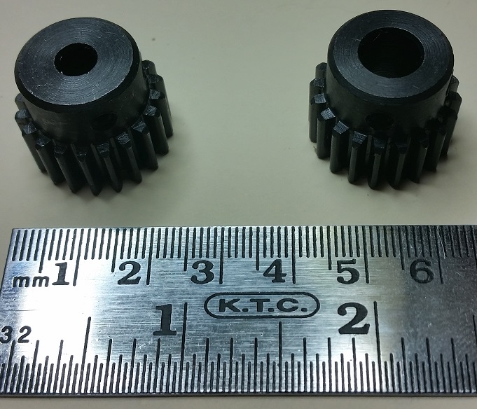
 The pinion gears we chose have 20 teeth with an outer diameter of 22mm. They stand about 18mm high.
The only difference between the two is the inner bore. One is 5mm. This is easy to interface with our chosen motor.
The second has an 8mm bore. This allows us to make a shaft, which can be centre drilled to allow the wires to pass through the slip ring.
The ones we have are also fitted with 2* 4mm grub screws to secure them to the shaft.
You can find these in various sizes by searching an internet for "Pinion Spur Gears". Or send us an e-mail for prices.
Bearings and Bearing blocks
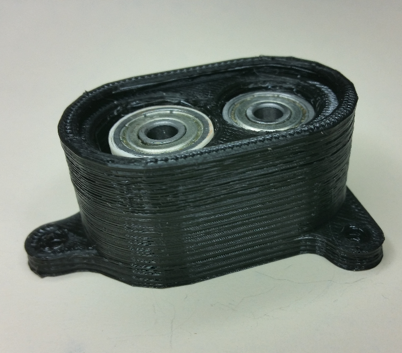
 The bearing blocks are designed and made on our 3D printer. It's a cheap model and is also playing up at the moment.
Extruding bobbles either at the end of one stroke or the beginning of the next.
Not exactly sure which yet.
Having spent days making fine adjustments, trying not to waste filament, we have it just good enough to print prototypes.
The bearing blocks are sized taking into account:
a) The size of the pinion gears and the distance between their centres.
b) The size of the shafts we will be using.
c) The dimensions of the bearings we will use.
The bearings we use currently are:
16 X 5 X 5mm. That is, 16mm overall diameter, 5mm bore, 5mm thickness.
This is the bearing through which the motor shaft passes.
18 X 8 X 5mm. That is, 18mm overall diameter, 8mm bore, 5mm thickness.
This is the bearing through which the wires pass, obviously slightly bigger to accomodate the wires.
The stepper motor

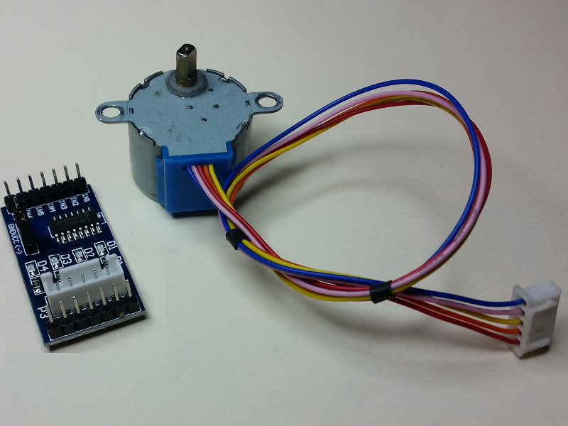
Our protoype uses the ubiquitous 28BYJ-48 stepper motor.
We also use the ULN2003 stepper driver module.
There seems to be several different types of these boards available.
We chose the type shown in the image because it has pcb pins at each end which provides a more robust mounting for our battle bots.
